The EOBD / OBDII 16-pin diagnostic connector (DLC)
Where is the connector?The EOBD connector is required by the Directive to be located within the passenger compartment of the car, within reach of the driver's seat. Tools should not be required to reveal the connector, but it may have a removeable cover over it. What does the connector look like?The connector has the following shape:  Which pins contacts should be present on the connector?Different pins on the connector are used by different manufacturers. There are 5 pinout combinations within the standard, each of which uses a specific communications protocol. These are listed below:
Note: For ISO/KWP2000 communications, pin 15 (L-line) is not always required. Pin 15 was used on earlier ISO/KWP2000 cars to "wake-up" the ECU before communication could begin on pin 7 (K-Line). Later cars tend to communicate using only pin 7 (K-Line). What are each of the pins used for?The pins are used as follows:
Additional pins may be wired on your car - these may be used by manufacturers for other purposes. Which protocol is used by each manufacturer?As a rough guide, the protocols are generally found on cars from the following manufacturers:
|
-
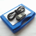
Ross-Tech VCDS HEX-V2 USB Package (3 VIN)
£ 225.00 -
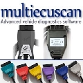
MultiECUScan Diagnostic Package (USB)
£ 129.95 -
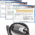
Gendan EngineCheck Pro USB package
£ 99.95 -
VW Audi USB KKL Diagnostic Interface Cable
£ 19.94 -
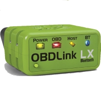
OBDLink LX EOBD OBD-II Bluetooth Interface
£ 94.96 -
MultiECUScan Package (CAN cars only)
£ 112.94 -
Foxwell NT200E Diagnostic Scan Tool
£ 34.94 -

Ross-Tech VCDS HEX-V2 USB Package (10 VIN)
£ 299.00 -
USB Engine package for 2001+ petrol, 2004+ diesel
£ 69.95 -
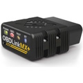
OBDLink MX+ EOBD OBD-II Bluetooth Interface
£ 129.95 -
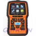
Foxwell NT301 Diagnostic Scan Tool
£ 69.00 -
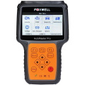
Foxwell NT680 Pro ALL Systems Scan Tool
£ 399.00 -
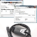
VauxCheck Software with vLinker FS USB interface
£ 64.94 -
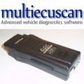
MultiECUScan Multiplex Package
£ 360.00 -

Ross-Tech VCDS HEX-V2 USB Package (Unlimited VIN)
£ 499.00 -

Foxwell NT680 Lite 4 Systems Scan Tool
£ 199.00 -
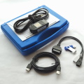
Ross-Tech VCDS HEX-V2 Enth. Plus Bundle (10 VIN)
£ 319.00 -
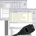
Opel-Scanner for Vauxhall and Opel cars
£ 229.00 -
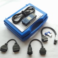
Ross-Tech VCDS HEX-NET Pro Plus Bundle (Unlimited)
£ 649.00 -
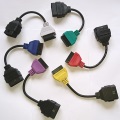
MultiECUScan Coloured Adaptor Cables
£ 31.94 -
Foxwell NT530+ Full Systems Scanner - Porsche
£ 164.00 -
EngineCheck Pro Diagnostics Software Download
£ 57.14 -

Foxwell NT530+ Full Systems - Peugeot/Citroën
£ 164.00 -
VauxCheck Diagnostics Software download
£ 30.59 -

Foxwell NT680 ALL Systems Scan Tool
£ 299.00 -
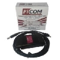
FiCOM Advanced Fiat & Alfa Diagnostics Package
£ 395.00 -
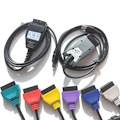
MultiECUScan Hardware Only Bundle
£ 80.00 -
MaxiECU for Vauxhall and Opel cars - Wireless
£ 135.00 -
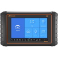
Foxwell i75TS Professional Diagnostic & TPMS Tool
£ 995.00 -
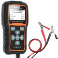
Foxwell BT715 12 / 24 Volt Battery Analyser
£ 85.00 -

OBDLink CX Bluetooth Interface for BimmerCode
£ 79.96 -
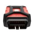
GS-911 USB Enthusiast Package 16-pin
£ 255.00 -
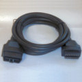
OBD-II / EOBD Extension Cable - 3 metre
£ 14.95 -
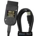
Ross-Tech VCDS HEX-V2 USB 3-VIN Package (No Case)
£ 222.00 -
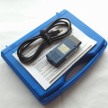
Ross-Tech VCDS HEX-NET Interface Package (10 VIN)
£ 430.00 -
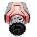
GS-911 WiFi Enthusiast Package 10-pin
£ 365.00 -

EngineCheck Pro Diagnostics Software Upgrade
£ 29.57 -
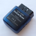
UniCarScan UCSI-2100 Bluetooth Interface
£ 51.50 -
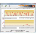
EngineCheck Diagnostics Software Download
£ 30.59 -

Foxwell NT530+ Full Systems Scan Tool - VAG cars
£ 164.00 -
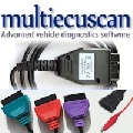
MultiECUScan Package (Non-CAN cars only)
£ 85.00 -
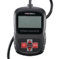
Foxwell BT100 12 Volt Battery Analyser
£ 44.95 -

Foxwell NT530+ Full Systems Scan Tool - BMW & Mini
£ 164.00 -

Foxwell NT530+ Full Systems - Jaguar Land Rover
£ 164.00 -

Foxwell NT530+ Full Systems Tool - Hyundai / Kia
£ 164.00 -

Ross-Tech VCDS HEX-V2 USB Home Plus Bundle (3 VIN)
£ 245.00 -
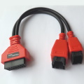
Security Gateway bypass adaptor for FCA vehicles
£ 24.95 -

Ross-Tech VCDS HEX-NET Package (Unlimited VIN)
£ 625.00 -

Foxwell NT530+ Full Systems Tool - Vauxhall / Opel
£ 164.00 -

Foxwell NT530+ Full Systems - Mercedes & Smart
£ 164.00 -
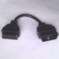
OBD-II / EOBD Extension Cable - 20cm
£ 12.50 -
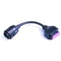
10-pin Adapter lead for GS911 with 16-pin plug
£ 19.94